Digital Workflow Integration In Modern AMT Manufacturing Facilities
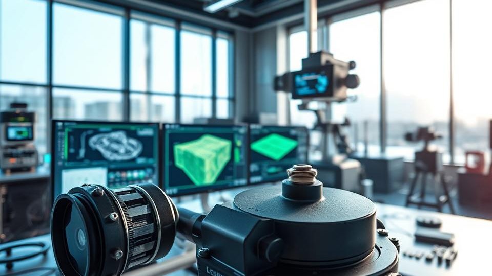
Precision LiDAR Components for Modern Mapping
Key insight: Across the United States, infrastructure surveys increasingly reuse airborne scanning data, reducing field time by more than 60% on many projects. This guide shows how to pick a https://amt-mat.com/precision-manufacturing-for-lidar-components-and-co-packaged-optics/ stack that meets real-world mapping needs across the United States.
We explain how to evaluate components, systems, and integration so professionals can specify a stack for modern mapping. You will understand how laser systems, optical elements, electronics, and software link up to gather data that supports geospatial and infrastructure workflows.
Follow an end-to-end workflow from planning through deployment and QA, including clear guidance on scanning parameters, detection thresholds, and timing decisions that influence accuracy and overall information yield. Expect practical guidance on budget, performance tiers, and growth paths so solutions scale from pilot to production without full system replacement.
This guide defines core terms, highlights safety and compliance aspects for eye-safe laser classes, and charts common deployment scenarios, including corridor mapping, city projects, construction, and utilities. By the conclusion, groups like surveyors, engineers, operators, and even fleet partners will be equipped to make defensible choices that cut rework and shorten time-to-field.
Main Takeaways
- Ways to assess components and integrated systems for mapping projects in the United States.
- The way lasers, optics, electronics, and software combine to gather valuable data.
- The workflow stages from initial planning to QA that influence overall data quality.
- How budget, upgrade strategies, and trade-offs among cost, performance, and time-to-field affect decisions.
- Considerations around safety, interoperability, and deployment contexts to support initial choices.
Understanding Precision LiDAR Components and Key Mapping Requirements
Effective mapping begins with clearly defined roles for each hardware element: how the beam is generated, steered, timed, and protected in the field.
Primary Parts and Functional Roles
The laser source produces carefully controlled pulses. A scanner or beam-steering module moves the beam across the scene. Receivers together with optics capture the returning energy and convert it into measurements.
A timing and synchronization unit stamps each return with precise time. A protective environmental housing shields the optics from dust, vibration, and harsh weather conditions.
From Pulses to a Point Cloud
From the source, laser light is emitted as short-duration pulses. The pulses impact surfaces and travel back to the receiver. Electronics measure the time-of-flight and signal amplitude. Subsequent processing turns those measurements into georeferenced point data that forms a point cloud.
| Component | Primary Benefit | Key Trade-offs | Field Notes |
|---|---|---|---|
| Laser source | Beam quality and usable range | Power vs. eye safety | Choose wavelengths for target reflectivity |
| Scanning method | FOV and overall coverage | More moving parts versus long-term reliability | Solid-state options reduce maintenance needs |
| Receiver module | Detection of low returns | Cost vs. sensitivity | High receiver gain improves detection on dark surfaces |
| Timing and housing | Stable, accurate timing | Weight and thermal needs | A robust enclosure helps maintain calibration over time |
Your choice of wavelength affects effective range, target reflectivity, and eye safety in remote sensing applications. You should balance timing precision, detector sensitivity, and survey speed to meet accuracy and coverage goals with https://amt-mat.com/business/mim/ceramic-injection-molding/.
How to Choose Precision LiDAR Components for Your System
First set measurable goals for the survey area, target objects, and the distances that drive system choices.
Set application objectives: list the mapping area, key objects, expected ranges, and environmental limits for each project. This helps you choose sensors and verify acceptance criteria for your applications.
Scanner and beam steering
Pick scanning or beam-steering methods based on coverage and model needs. Mechanical scanners give wide field coverage. Solid-state options reduce moving parts for both vehicle and aerial deployments.
Receiver Performance, Noise, and Timing
Evaluate receiver sensitivity and noise handling to protect weak returns. Verify detection thresholds and front-end design so measurements remain stable in bright or low-signal environments.
Integration and Data Throughput
Set synchronization methods—PPS or PTP—to align lidar timestamps with GNSS/INS and cameras. Match throughput to storage and processing so data flows without gaps during long surveys.
- Build a requirements matrix linking area, targets, distances, and outputs to measurable acceptance criteria.
- Specify lasers and optics for reflectivity and temperature range while keeping eye-safe margins.
- Confirm mechanical fit, power needs, and thermal design on vehicles and aerial platforms.
- Define calibration procedures, redundancy levels, and data formats so analytics teams receive clean inputs.
How to Validate, Secure, and Deploy on Vehicles and Aerial Systems
Following a systematic validation plan cuts guesswork and maintains surveys within specified accuracy targets. First confirm alignment and timing parameters before starting full production operations.
Calibrating the system
Conduct boresight alignment between the lidar, GNSS/INS, and cameras. Execute measurement-unit checks with ground control and validate known features to confirm range and angular precision.
Include vibration characterization and range checks for both vehicles and aerial models. Record outcomes and certify each unit as field-ready before you start data collection.
Safety and compliance
Choose eye-safe lasers and clearly label each enclosure. Train field teams on light detection and ranging procedures and maintain operational logs to demonstrate compliance during audits.
Applied fleet scenarios
Standardize mounting hardware, power distribution, and quick-release brackets so lidar systems can be installed on vehicles rapidly.
Plan routes, define collection speeds, and rotate storage devices so each system holds accuracy thresholds while maximizing per-shift coverage.
- Calibration workflow: boresight alignment, measurement checks, and control verification.
- Safety plan: use eye-safe lasers, maintain marked enclosures, provide training, and keep audit logs.
- Validation: vibration tests, range verification, day/night detection checks.
- Fleet model: consistent mounting hardware, power interfaces, and quick installation/removal procedures.
- Monitoring & QA: system health logging, automated trajectory workflows, strip-to-strip alignment, and differencing against control points.
| Application | Key Validation Step | Result |
|---|---|---|
| Ground vehicle mapping | Testing vibration response and mount stability | Consistent measurements at speed |
| Aerial surveys | Range & timing sync check | Georeferenced point accuracy |
| Urban/highway | Reflectivity and occlusion trials | Reduced multipath and clearer returns |
Document your procedures and train drivers and technicians so they can solve routine issues and escalate complex ones quickly. Keep a governance checklist for briefings, route permissions, incident reports, and data retention to ensure safe, auditable operations.
Conclusion
Conclude with a practical plan that moves teams from AMT requirements to validated data collection across vehicles and flights. Start by drafting a vendor-neutral requirement set, and compare a minimum of two lidar systems for each category.
Find the right balance among light and laser choices, scanning plans, and receiver settings to satisfy your mapping and detection goals. Use timing discipline and sync to keep each lidar system producing consistent point and trajectory outputs for point cloud deliverables.
Begin with a pilot on several vehicles: validate ranges and distances across varied environments, follow the calibration and safety checklist, and then scale up with planned maintenance and data collection practices. Such a disciplined approach keeps systems, models, and operations aligned, helping teams provide dependable mapping solutions on time and on budget.